Finisar FTLF8529P3BCV Fibre Channel Transceiver Module

- In Stock:1Need more?Stock Levels
This stock level is real time and accurate. This quantity is available for same-day shipment. Larger quantities can take up to a week to ship. Call us for larger quantities that you need urgently.
- 1 Year DiscTechWarrantyProduct Warranties Explained
The product has a DiscTech warranty for the time period specified. View our limited warranty
| Interface Types: | Fibre Channel - Internal - Arbitrated Loop ASA II |
| Electrical Interface: | FC-AL - 8Gbps |
| Voltage: | 3.3V |
Description
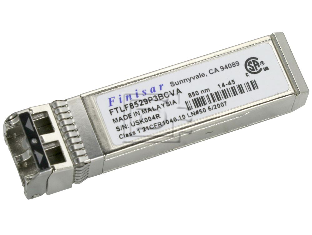
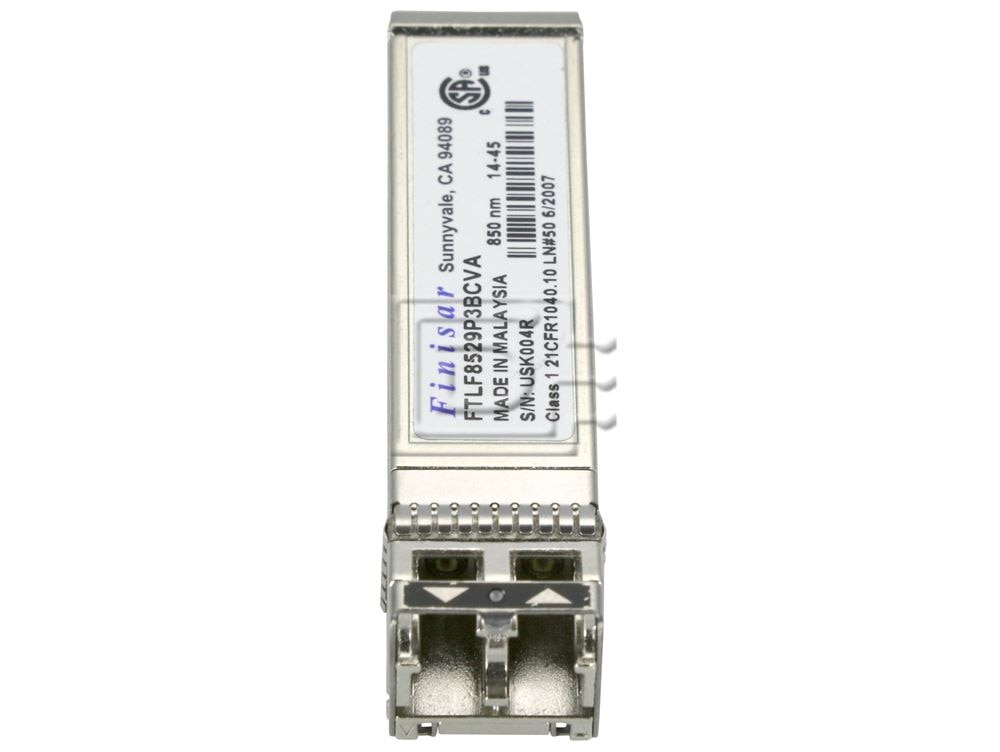
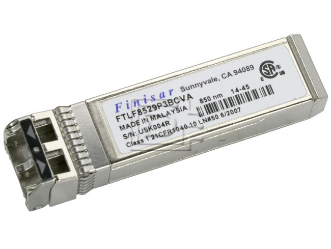
Finisar FTLF8529P3BCV 16GB Fibre Channel Transceiver Module for 850nm wavelength LC SFP+ duplex Connector - Brand New
Finisar FTLF8529P3BCV 16GB Fibre Channel Transceiver Module for 850nm wavelength LC SFP+ duplex Connector - Brand New
Product Features
- Up to 14.025 Gb/s bi-directional data links
- Hot-pluggable SFP+ footprint
- Built-in digital diagnostic functions
- Built-in CDR with shut off control
- 850nm Oxide VCSEL laser transmitter
- Duplex LC connector
- RoHS compliant and Lead Free
- 35m on 50/125µm MMF
- 100m on high-bandwidth 50/125um (OM3) MMF
- Metal enclosure, for lower EMI
- Single 3.3V power supply
- Operating temperature range: 0°C to 70°C
Applications
- Tri-Rate 4.25/8.5/14.025 Gb/s Fibre Channel
Finisar’s FTLF8529P3BCV SFP+ transceivers are designed for use in Fibre Channel links up to 14.025 Gb/s data rate over multimode fiber. They are compliant with FC-PI-5 Rev. 6.00, SFF-8472 Rev 11.0 and SFF-8081, and compatible with SFF-8432 and applicable portions of SFF-8431 Rev. 4.1. The optical transceiver is compliant per the RoHS Directive 2011/65/EU.
Regulatory Compliance
Finisar transceivers are Class 1 Laser Products and comply with US FDA regulations. These products are certified by TÜV and CSA to meet the Class 1 eye safety requirements of EN (IEC) 60825 and the electrical safety requirements of EN (IEC) 60950. Copies of certificates are available at Finisar Corporation upon request.
Digital Diagnostic Functions
Finisar FTLF8529P3BCV SFP+ transceivers support the 2-wire serial communication protocol as defined in the SFP MSAf . It is very closely related to the E2 PROM defined in the GBIC standard, with the same electrical specifications.
The standard SFP serial ID provides access to identification information that describes the transceiver’s capabilities, standard interfaces, manufacturer, and other information.
Additionally, Finisar SFP transceivers provide a enhanced digital diagnostic monitoring interface, which allows real-time access to device operating parameters such as transceiver temperature, laser bias current, transmitted optical power, received optical power and transceiver supply voltage. It also defines a sophisticated system of alarm and warning flags, which alerts end-users when particular operating parameters are outside of a factory set normal range.
The SFP MSA defines a 256-byte memory map in E2 PROM that is accessible over a 2-wire serial interface at the 8 bit address 1010000X (A0h). The digital diagnostic monitoring interface makes use of the 8 bit address 1010001X (A2h), so the originally defined serial ID memory map remains unchanged. The interface is identical to, and is thus fully backward compatible with both the GBIC Specification and the SFP Multi Source Agreement. The complete interface is described in Finisar Application Note AN-2030: “Digital Diagnostics Monitoring Interface for SFP Optical Transceivers”.
The operating and diagnostics information is monitored and reported by a Digital Diagnostics Transceiver Controller (DDTC) inside the transceiver, which is accessed through a 2-wire serial interface. When the serial protocol is activated, the serial clock signal (SCL, Mod Def 1) is generated by the host. The positive edge clocks data into the SFP transceiver into those segments of the E2 PROM that are not write-protected. The negative edge clocks data from the SFP transceiver. The serial data signal (SDA, Mod Def 2) is bi-directional for serial data transfer. The host uses SDA in conjunction with SCL to mark the start and end of serial protocol activation. The memories are organized as a series of 8-bit data words that can be addressed individually or sequentially.
For more information, please see the SFP MSA documentation and Finisar Application Note AN- 2030.
Please note that evaluation board FDB-1027 is available with Finisar ModDEMO software that allows simple to use communication over the 2-wire serial interface.
Digital Diagnostic Specifications
FTLF8529P3BCV transceivers can be used in host systems that require either internally or externally calibrated digital diagnostics.
Mechanical Specifications
Finisar’s FTLF8529P3BCV SFP+ transceivers are compatible with the SFF-8432b specification for improved pluggable form factor.
Compatibility
Compatible with SFF-8432 and applicable portions of SFF-8431
Specifications
| 14 Gb/s Short-Wavelength SFP+ Transceiver | |
|---|---|
| Model Number | FTLF8529P3BCV |
| PARAMETER | |
| Maximum Supply Voltage | |
| Case Operating Temperatue Commercial | |
| Case Operating Temperatue Extended | |
| Relative Humidity (Non-condensing) | |
| Supply Voltage | |
| Supply Current | |
| ELECTRICAL TRANSMITTER | |
| Input differential impedance | |
| Single ended data input swing | |
| Transmit Disable Voltage | |
| Transmit Enable Voltage | |
| ELECTRICAL RECEIVER | |
| Single ended data output swing | |
| LOS Fault | |
| LOS Normal | |
| Power Supply Rejection | |
| Deterministic Jitter @ 8.5 Gb/s | |
| Deterministic Jitter @ 14.025 Gb/s | |
| OPTICAL TRANSMITTER | |
| Avergare Output Output. Power: 50 or 62.5 MMF | |
| Optical Wavelength | |
| Spectral Width (RMS) @ 14.025Gb/s | |
| Optical Modulation Amplitude @ 4.25 Gb/s | |
| Optical Modulation Amplitude @ 8.5 Gb/s | |
| Optical Modulation Amplitude @ 14.025 Gb/s | |
| Optical Rise/Fall Time @ 4.25 Gb/s | |
| Transmitter Waveform and Dispersion Penalty @ 8.5 Gb/s | |
| Vertical Eye Closure Penalty @ 14.025 Gb/s | |
| Relative Intensity Noise | |
| OPTICAL RECEIVER | |
| Receiver OMA Sensitivity = 4.25 Gb/s | |
| Receiver OMA Sensitivity = 8.5 Gb/s | |
| Receiver OMA Sensitivity = 14.025 Gb/s | |
| Average Receiver Power | |
| Optical Center Wavelength | |
| Optical Return Loss | |
| LOS De-Assert | |
| LOS Assert | |
| LOS Hysteresis | |
| GENERAL SPECIFICATION | |
| Data Rate | 8.25 14.025 |
| Bit Error Rate | |
| Fiber Length on 50/125µm MMF | 50 35 4 5 |
| Fiber Length on 50/125µm highbandwidth (OM3) MMF | 150 100 4 5 |
| GENERAL SPECIFICATION | |
| Case Operating Temperature Commercial | |
| Case Operating Temperature Extended | |
| Storage Temperature | |
| DIGITAL DIAGNOSTIC ACCURACY | |
| Internally measured transceiver temperature | |
| Internally measured transceiver supply voltage | |
| Measured TX bias current | |
| Measured TX output power | |
| Measured RX received average optical power | |
| DIGITAL DIAGNOSTIC DYNAMIC RANGE FOR RATED ACCURACY | |
| Internally measured transceiver temperature | |
| Internally measured transceiver supply voltage | |
| Measured TX bias current | |
| Measured TX output power | |
| Measured RX received average optical power | |
| DIGITAL DIAGNOSTIC MAX REPORTING RANGE | |
| Internally measured transceiver temperature | |
| Internally measured transceiver supply voltage | |
| Measured TX bias current | |
| Measured TX output power | |
| Measured RX received average optical power | |
Click here to view the manufacturer's item description/brochure
ROHS Compliant
Weight: 0.5 lb
Warranty: 1 Year DiscTech
Condition
The product is brand new.
Warranty
1 Year DiscTech Warranty